Building an Audio Input Switcher with ChatGPT und Claude
Why?
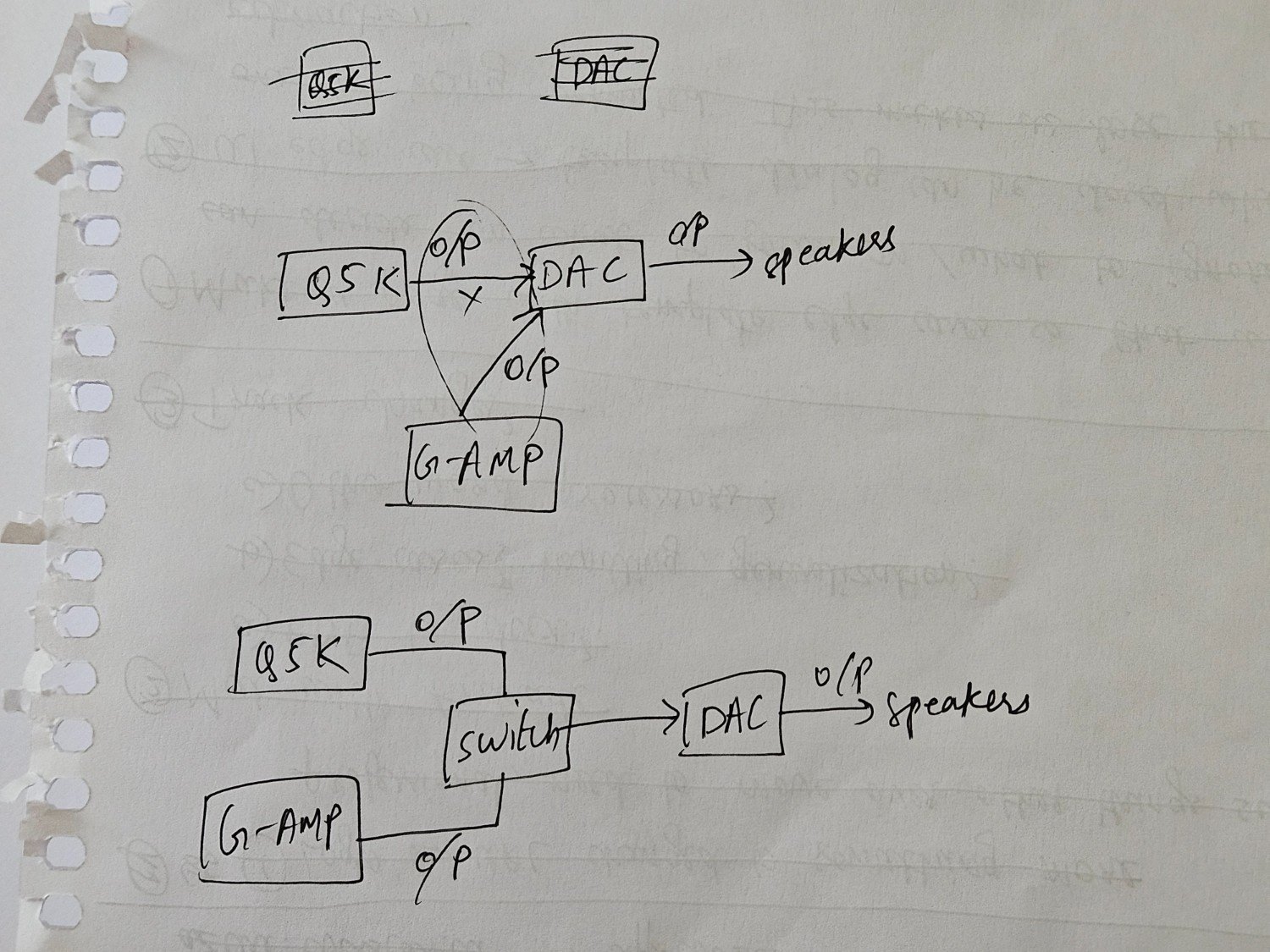
I wanted something with two audio inputs, one output, and a switch for switching between them. But alas, audio switchers which cater to that use case literally do not exist (as of writing this article). I have searched far and wide and the best thing I got was an audio mixer — which can definitely act as a switcher or import one, both being expensive. The next best option was to just build one from scratch.
Before jumping into that, I would like to tell a tale of two LLMs giving me two different ways to build this. I initially decided to design everything with Claude because my assumption was that since it's good with code, that should extrapolate and result in good hardware designs too. But I had a hunch and decided to ask ChatGPT as well and that resulted in a fork in the road: Claude told me to add coupling capacitors while ChatGPT refused it because according to it, adding those caps would affect the low-end of the frequency response and I for sure would not like that.
So with my sparse knowledge about RC circuits which I barely remember on account of it being over half a decade old, I chose to go with ChatGPT. I definitely don't hear any differences if I compare the signal going directly from my DAC into my pre-amp v/s through the audio switcher so I think it works well enough.
Components
- 3D printer / printing service to print this model
- 4x M2.5 X 4mm brass threaded inserts
- 4x M2.5 X 4mm screws, I chose countersunk philips because the model supports it
- 3x panel mount 3.5 mm jacks
- 1x DPDT switch
- 4x 100 Ω resistors (or any value between 50 Ω -> 220 Ω)
- Bleed resistors: 2x 100kΩ resistors (or any value between 47kΩ -> 220kΩ)
- 24 AWG wires, I didn't have these so I grabbed an unused USB cable from the hoarded cable container (as one acquires over the course of his life), and cut them to desired lengths
- Soldering station
- Solder tin
- Solder flux
- Helping hands (definitely get these if you don't have one)
- Multimeter
Procedure
The procedure is trivial if you know your way around soldering components but I particularly got confused about connecting the bleed resistors to ground and how that connected to the common star ground point. I'll be going over this amongst other things:
- Having colour coded wires is very helpful as you don't want your channels reversed. Double check your polarity at all steps
- Since the enclosure is small, make sure that the wires aren't too small/large as this can lead to frustrations. I decided to not use cables at all to connect the resistors which also helped in minimising the things I had to solder
- Check for the common (
COM) terminal in the DPDT switch before deciding to wire it up - When adding the brass inserts, make sure to let the heat do the job and not the pressure
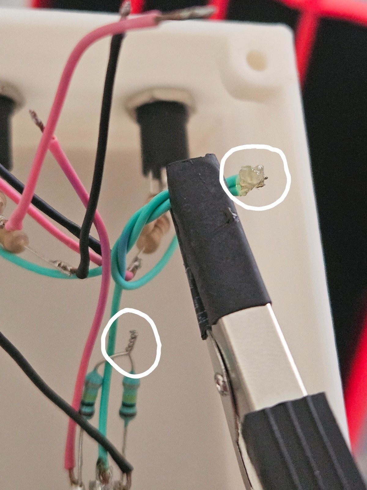
Star Ground Point
Solder the bleed resistors to the L and R terminals of the output jack and then connect them together
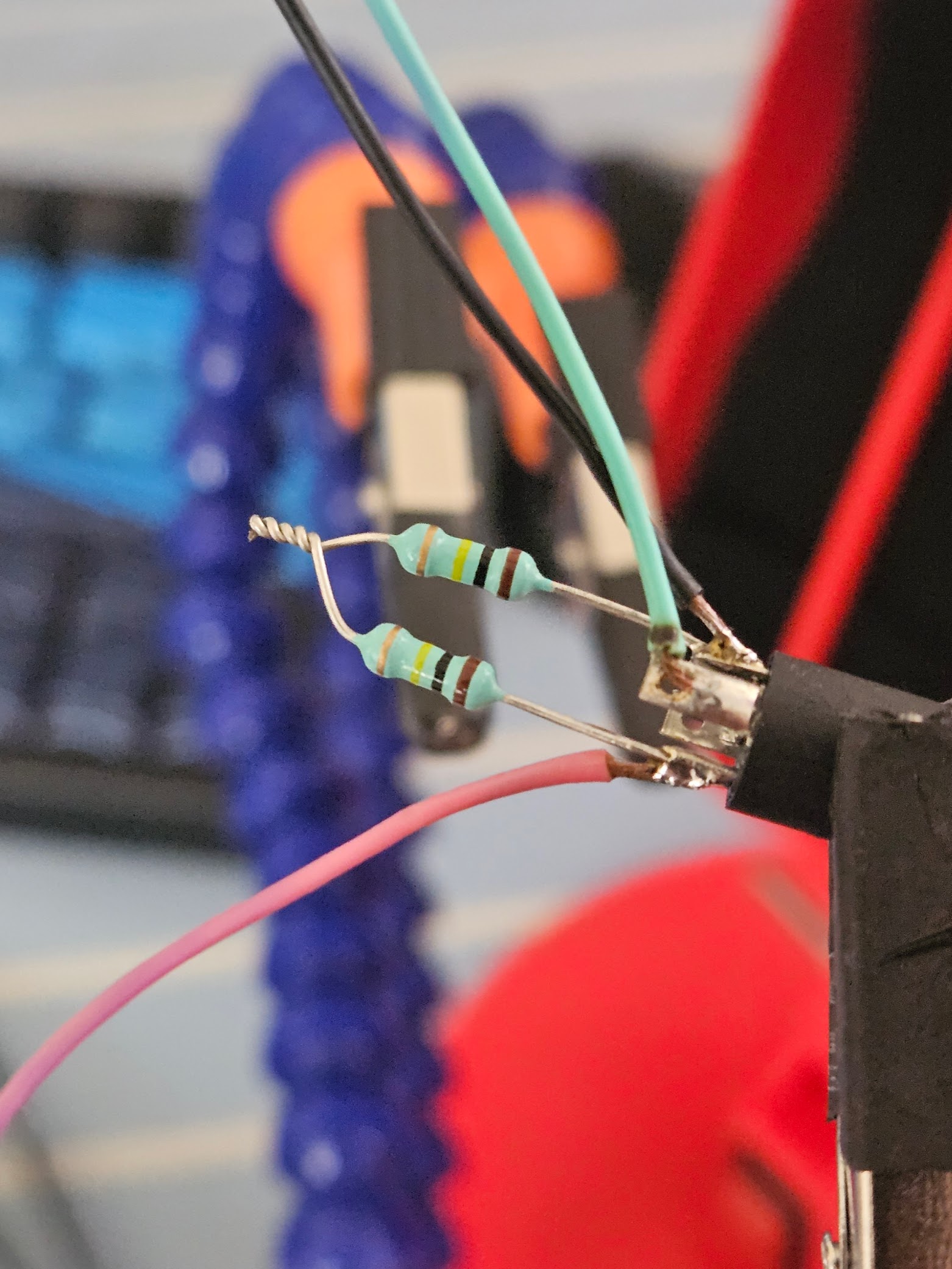
Grab all the grounds from all the three jacks and solder them. After that, solder that to the bleed resistors junction you just made. That's the common star ground point!
Final Assembly
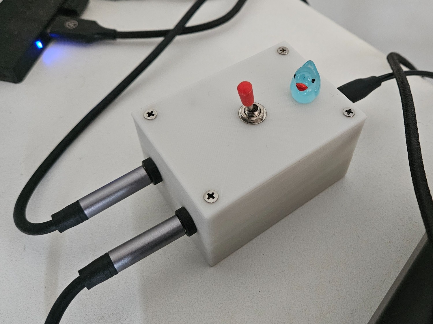
Once you're done with everything, you should have something which looks like this (except with all the brass inserts in)
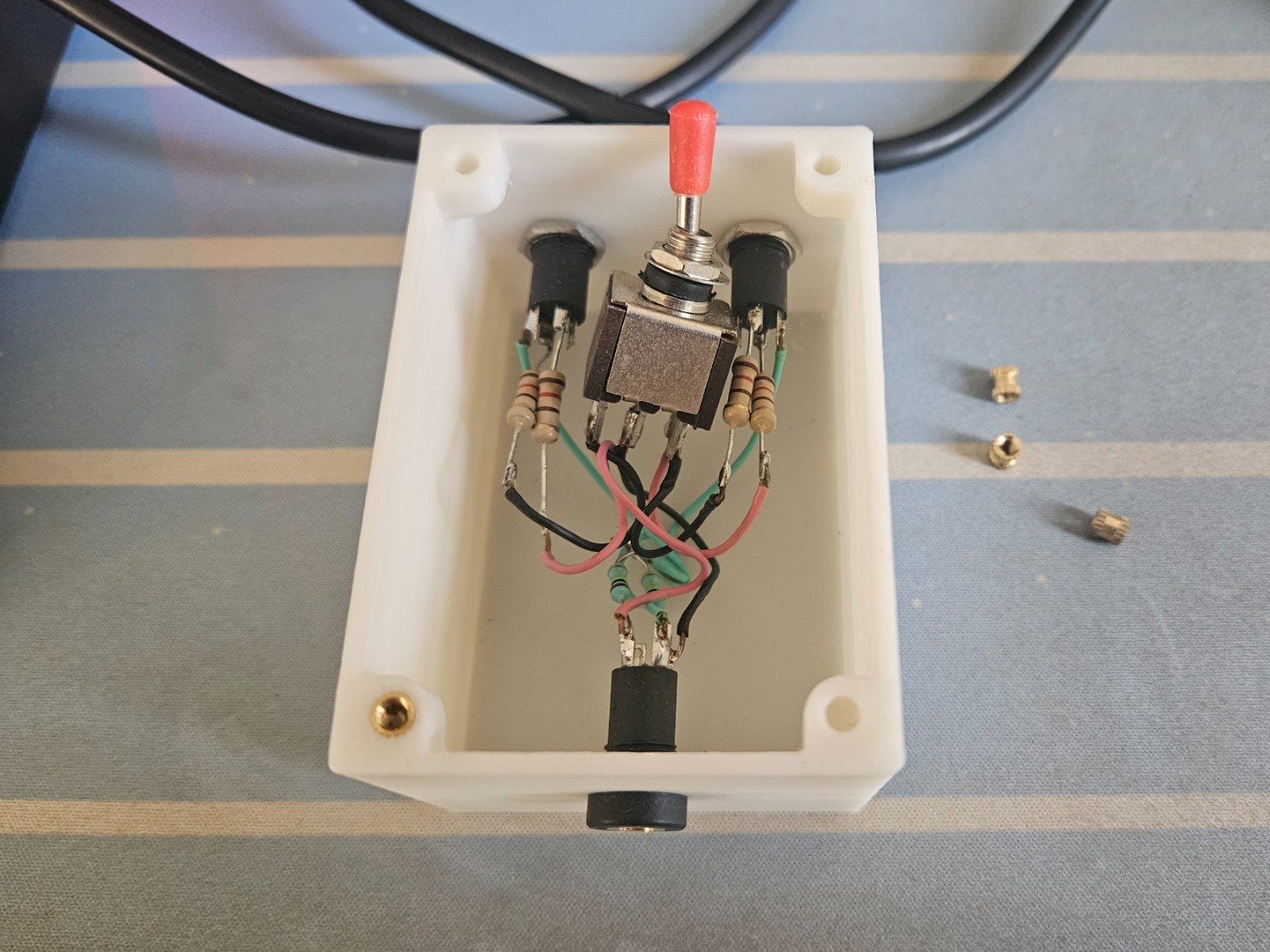
Voila!
The switcher in action, one flip and my speakers connects to my audio interface
Disclaimer
Everything here is written by a 🧬, including the em-dashes.